Ever since I started rebuilding Quad ESL's I wanted to try to build my own ESL's. The Quad ESL's are fundamentally flawed in several ways. First, they are sectionalized. This does improve dispersion, and was necessary to get the efficiency up for use with the low powered amplifiers of the day. But this sectionalization requires a crossover network and can cause response anomalies (however the Quad ESL crossover was very well done). The Quad ESL's also play through a dust cover, which acts as a passive radiator of sorts. Aside from the additional frequency response anomalies, the dust covers can also cause rattles and buzzes. The Quad ESL is a fragile speaker is somewhat limited in dynamics and bass authority. In general the Quad ESL is a wonderful speaker, but I have always thought that some of it's fundamental limitations could be overcome while still retaining that amazing clarity and neutrality that has made it legendary. This page is dedicated to my quest for a quad-like sound with more macro-dynamics and authority.
My initial design goals were to produce a speaker which could cover the entire audible range, and not be limited in absolute SPL (to the extent the original Quad ESL is). I wanted to use a single ESL panel to cover all the critical audible range. I wanted to use a dynamic bass unit to overcome the limitations of dipoles in the bass area, but I wanted to keep that dynamic driver crossover as low as possible to make it as non-intrusive as possible. For this initial project, final size and weight were a secondary concern.
This is my initial design, and so far is very promising. My initial paper design was to build a 48" x 18" panel and use a transmission line loaded woofer for the bass. I wasn't sure exactly where the woofer would get cut off. I decided to build panels, then taylor the woofer to match the panels as needed.
A few years ago, I tried building some panels with Lincain TM and Lexan spacers. I didn't like the Lincain at all, it's very thin and prone to resonate. The Lexan spacers work well but epoxy doesn't like to stick to either the Lincain or the Lexan very well. So I decided to try to build a set of panels either out of wire stators (like the Audiostatic ES50 speakers I had rebuilt) or from more standard and thicker perforated metal. I also wanted to try using the eurathane based acrylic adhesive double sided foam tape from 3M as both spacers and glue. This technique is used by many commercial ESL producers and seems to work quite well.
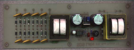
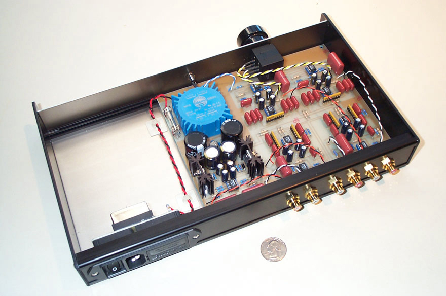
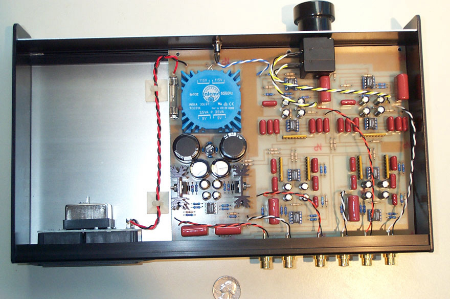
Back in late 1998, I had purchased some very nice step-up transformers from The ESL Information Exchange and I designed my own high voltage supplies. These supplies are a fairly clever design. The standard household power (110 or 220) is brought to the board and stepped down, rectified and filtered to form low voltage DC (15 volts or so). This DC powers a small switching supply whose frequency is tuned to the resonant point of a secondary small rectifier transformer wired backwards. The amplitude of the driving signal is regulated and adjustable to variable output levels. Because this signal is at the resonant point of the transformer, the output is about twice the voltage level it would be if another frequency had been chosen. The output of this second transformer goes to a standard Cockroft-Walton voltage multiplier. It may seem odd, to drop the line voltage, rectify it, regulate it, chop it, and then step it up. but by removing the first transformer, a plug-in transformer (wall-wart) can be used, and if a DC power supply is used, the rectifier and filter cap can also be removed. This may be a big help if I ever decide to sell a speaker based on this design because I can use UL (or CE) listed power supplies and not have to worry about getting my speaker UL listed. Because the switched signal which is rectified is such a high voltage, the filter caps in the Cockroft-Walton multiplier filter the noise out very well. Here's a photo and the plans for my high voltage supplies:
These speakers started with four nice pieces of perforated aluminum purchased from a local metal scrap yard here in Albuquerque (Koenigs). The pieces I purchased were 48" x 20.375"; the perfect size for what I wanted, I didn't even have to cut them. I got the metal for $2.00 a square foot. After degreasing it and painting it black (no easy task), I was ready to try my hand at building. I constructed these panels using 0.125" thick 1" wide 3M foam tape. I used central dots to support the 1/2 mil MylarTM rather than a solid strip dividing the panel into two cells. This acts to keep the resonant point of the Mylar low while still supporting it for good panel stability. Even with the dot technique I still have a 1:75 diaphragm to stator spacing or better. A movie of the build-up process is available below for those of you interested. It's fairly large (7.4 meg), so be warned.

An ESL Panel Construction Slide Show
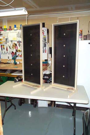
After the panels were constructed, it was time to see what they measured and sounded like. with the help of Loudspeaker Lab I was able to get some good measurements of these panels. I constructed some temporary frames to hold the panels and electronics.
|
|
The initial measurements showed that I had just built the world's largest tweeter. The pressure feedback around the panel started to roll the panels off (6dB per octave) right at about 1 KHz. This is an in-room sweep with no time window gating. A graph of this response can be seen be clicking here. A semi-echoic response is shown here (high frequency differences in the panels is a function of my test setup). At this point is was pretty happy with the panels and ready to construct a set of bass cabinets.
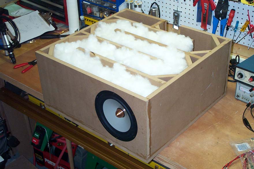
I decided to try the very nifty looking (cosmetically and specifications) Seas Excel W22 8" woofers. I've always been drawn to transmission line woofer loadings. The un-boxiness of them and the low frequency supplement below Fs is very attractive to me. So I decided to try a transmission line enclosure for the woofers. They have an Fs of 27 Hz and an Sd of 220 square cm. This meant that my line would need to be about 9 feet long and the total box area would be on the order 4 cubic feet (including baffles). This is a huge box, but I wanted maximum performance out of my first attempt; plus MDF is cheap. I used impedance measurements of the woofer in the box to help determine the proper stuffing density along with some basic stuffing rules-of-thumb. The impedance plot of the woofer in the unstuffed TL box is shown here. This has the appearance of a ported enclosure and several resonant spikes due to the parallel walls. I added stuffing until the two main impedance peaks had just dissapeared. This was a bit of a judgement call and I may have gone a touch farther than a could have. I ended up using about 24 oz of dacron poly-fill. The rule of thumb for TL stuffing said that I should use even more. The impedance plot of the woofer in the 24 oz. stuffed TL box is shown here. Note that this impedance curve now looks like an acoustic suspension enclosure. The plans for this woofer enclosure are provided below.
My initial design idea was to cross over the woofer at about 700 Hz and fairly steeply to fill in that pressure rolloff region of the panel below 1 KHz. But I built a 700 Hz passive crossover and started listening to just the woofer, and I felt that there was to much musical information coming out of the woofer. This crossover point was clearly too high. I didn't want to have any midrange or midbass overlap between the panel and the dynamic driver. This conceptually made sense to me too. The more of the audible range that I could get covered seamlessly with the panel the better off I was. So I decided to see if I could equalize the panel to compensate for the pressure rolloff.
Because of my construction technique with the central dots rather than two cells, my panel resonant point is way down around 30 Hz. This means that I can run this panel essentially full range with only a shelving EQ circuit to take care of that rolloff. So I built a simple shelving circuit using a single op-amp (per channel) and put that circuit between my pre-amp and amp. I then started listening and was very impressed at the potential of these panels. There was still a strain when they would try to reproduce bass, but they were remarkably adept even full range. A measurement of this shelving circuit with the panel is shown here. The shelving circuit has about 20 dB of total gain, and a corner frequency of about 725 Hz.
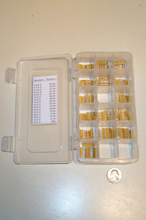
Because the panels were so promising full-range, I decided that I could safely go pretty low crossing over to the dynamic bass driver. Due to my success with the shelving circuit, I decided that doing all the crossovers active would really work well and allow my amplifiers to really control the drivers. Given how nasty an impedance, the ESL panel is (see here), I thought that an active crossover was an extra good idea. My initial design was to cross over the panel and the woofer at 200 Hz using 4th order Linkwitz-Riley crossovers. However I did not have enough resistors to complete the needed circuits, and I had to fall back to another value. It turned out that I had plenty of resistors to get me a 160 Hz crossover point, and this is what I tried. After listening to the woofer with a 160 Hz 4th order low-pass crossover, I felt pretty good that this was a good crossover point. the woofer is adding weight and foundation without imposing it's character on any of the musical detail. This is exactly what I wanted. At this point it was time to do some more measurements. A measurement of one of the woofers in my room and the ideal 4th order crossover curve is shown here. You can see the room standing waves, but the crossover is knocking it down pretty well. The panel measurement with the shelving eq and 4th order high-pass at 160 Hz is shown here (the high frequency rolloff is due to mic placement). A semi-echoic measurement of both the panel and the bass module is shown here.
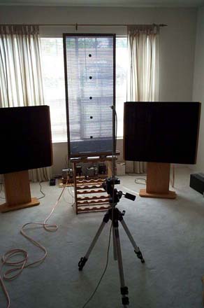
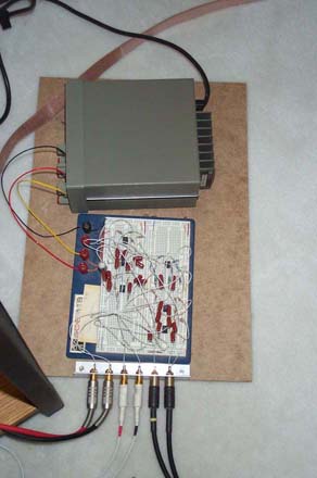
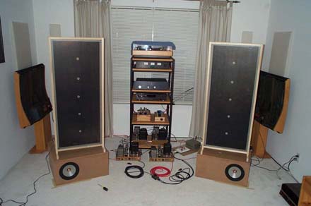
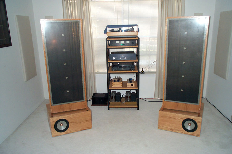
A couple pictures of my first listening test (powered by a quartet of Heath W5M 20 watt amplifiers) is shown below, as is a picture of my bread-boarded active crossover. Below is also a link to the schematic of my initial crossover design.
|
|
The initial listening tests were shocking. This is a speaker which is unlike any other I've heard. It has a clarity and a transparency that is almost too lifelike. It is has an ease and a crispness that I had always thought the Quad ESL had in spades, but it turns out that the Quad is only about 80% of the way there. The treble is just "right" without being harsh or silibant. Dynamics which are typically ESL's weak point are also amazing. Acoustic bass is reproduced with a clarity and a realism that I've never heard in a loudspeaker before. The weak point to this speaker system is the amazing directionality, these speakers put out laser beams of sound. If you get up from the listening chair, it's like somebody unhooked them. I believe that this very directed energy is one of the reasons for the good dynamic presentation. To get a feel for just how directional these things are, here is a couple polar plots. The first plot is the panel rotated in 1 degree increments (yes, one degree!). This plot can be seen here. The second polar plot shows a more typical dynamic speaker polar range. I stopped this test at a rotation of 30 degrees because it was getting silly. The plot can be seen here.
I am continuing to tweak the design and crossover to try to maximize it's potential. I am also building a more permanent active crossover, and planning to repackage the bass units and panels in a much more aesthetically pleasing way.

September 21, 2002 Update:
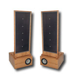
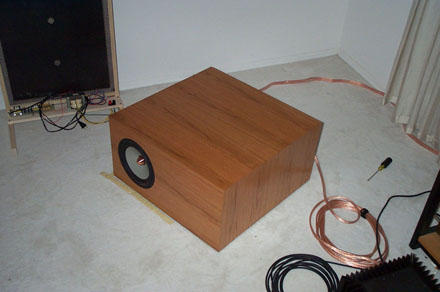
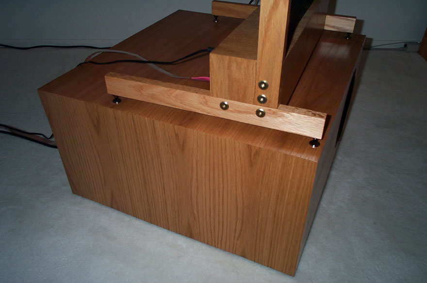
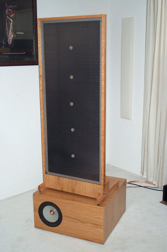
I have finished the bass modules, they have been veneered with red oak. I used 10 mil paper backed veneer and it was a lot easier and more forgiving than I had imagined. Before veneering, I implanted magnets on the front baffle for attaching a grille. The bass units sound the same, but look a whole lot better. this was also my first attempt with a HVLP spray gun and spray lacquer. I have to say that spraying on wood finishes is really the way to go. I get better results than I've ever gotten with a brush and it took a lot less time too. Here's a picture of a completed bass module. It's still big, and it's still heavy, but it's looking a lot more like a speaker (or piece of furniture) and less like some sort of MDF science project creation.
The other major accomplishment to happen in the last week or so is the completion of the final active crossover which will drive these things. It's based on the same circuit that used to appear above. I designed a circuit board for the unit, and put it in a Sescom case. It uses SIP resistor packs to set the crossover frequency. These resistor packs are on sockets and can be replaced to set whatever crossover point is needed. I tried higher and lower points with my current ESL's and I keep coming back to 160 Hz as the best crossover point, it was a good guess I'd say.
It's got an oversized power supply and good strong regulation. The op-amps are all Burr Brown OPA-2134's which are very good sounding, especially in this unity (or nearly) gain configuration. The panel portion of the box is a 24 dB/octave Linkwitz-Riley high pass filter followed by a shelving EQ (to compensate for the pressure rolloff which all dipoles exhibit) and then a unity gain inverter (to invert the inverting shelf circuit). The bass leg has a 24 dB/octave Linkwitz-Riley low pass filter followed by a bass level potentiometer. this is followed by a gain stage and then an all-pass network for phase aligning the bass driver with the panel.
The schematic, circuit board artwork and a parts list are provided in the Acrobat file below. Some pictures of the finished crossover are also shown below.

|
|
|
|
|
|
September 24, 2002 Update:
I have been working on a set of replacement frames for the poplar test frames that are shown in the above shots of the ESL panels. I finally got them finished this evening. I'm not completely satisfied with the looks of them, but they will do for now. After all this is a finished prototype, and not my absolute final design.
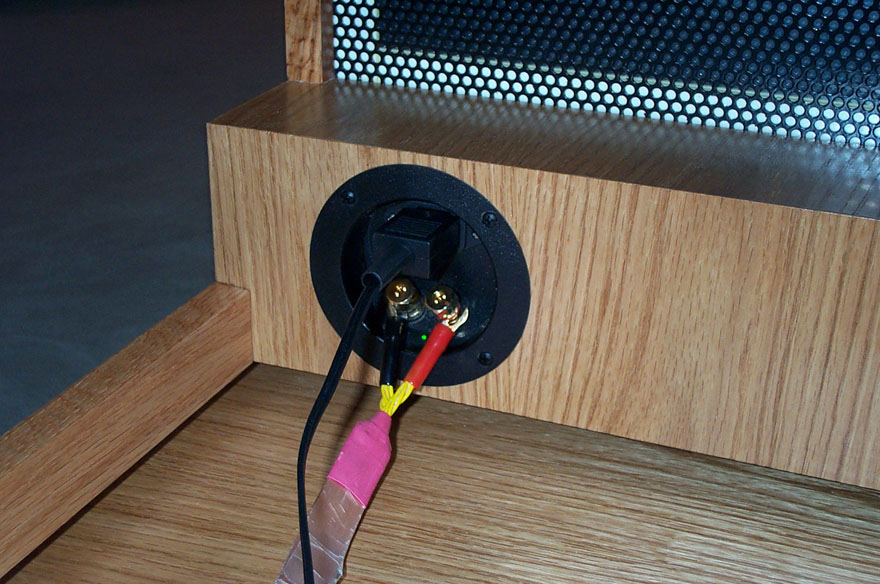
I modified a plastic input cup (for the speaker wire connection) to include an IEC connector and a power indicator LED. There is a lot of extra room at the top of one of those input cups, and this is a perfect use for that space.
The only thing I have left to do is build the grille frames, and install the grille cloth on the frames. I'm using rare-earth magnets to hold both the bass module grille and the panel grilles in place. This has been working a lot better for me than any other method I've tried before.
|
|
|

|
|
March 19, 2003 Update
I've been rebuilding Quad ESL-57 and ESL-63 electrostatic speakers using some really nice 3.8 micron thick polyester film purchased from ER Audio. I decided to have a fresh set of aluminum perforated metal stator material powder coated, to try this super thin film. This film is roughly twenty five times tinner than a human hair. The mass of the 16" x 46" diaphragm is about 2.5 grams. After building a set of panels with this film, and listening to them, they turned out to be HARSH. It turns out that the ESL Information Exchange transformers have a bit of leakage inductance problem which is causing a rising treble response problem. This makes for the most detailed and revealing speakers I've ever heard, but a bit "teeth drilling".
All transformers have some leakage inductance and will cause a resonant peak in the ESL response. The frequency response change can be seen here. A resistor in series with the primary will damp this impedance peak and flatten the treble response. However, the magnitude of the peak in this case indicates that these transformers may have a bit of a problem. I tried a number of different resistor values in series with the transformer primary, the frequency response of these changes can be seen here
It is interesting to note that the original panels also exhibited this rising response, but the mass of the diaphragm caused the panel to start rolling off as the frequency response started increasing. However there was still some frequency response anomalies. The frequency response of the new panels with the shunt resistor versus the old thick mylar panels can be seen here.
The impedance of the panel with the shunt resistor is also slightly better, as it doesn't drop to nearly zero at high frequencies, as seen here. However, ESL's are still very nasty loads as compared to standard cone and dome speakers as seen here.
As with most ESL's, precise consistent panels are easy to construct. This pair of panels both measured at the same point in the room and with the panels positioned as closely the same as possible are shown here. The panels aren't positioned exactly the same, so there is a slight deviation in response. The panels measured at their standard listening positions with the measurement microphone at the listening position are shown here.