
|
|
|
|
|
|
|
|
|
|
|
|
|
|
|
|
|
|
|
|
|
|
|
|
|

|
|
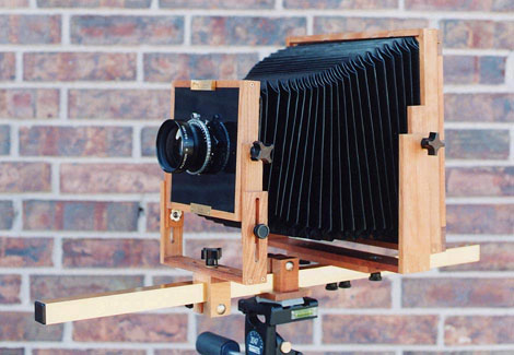
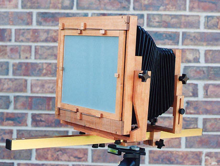
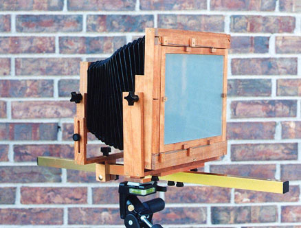
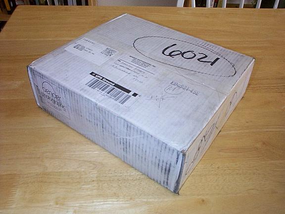
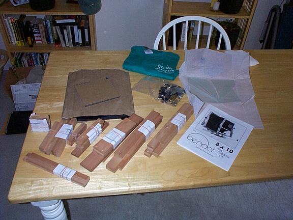
NOTE: These tips and review are also shown at Bender Photo with Jay Bender's comments. Please also read his commentary. These are comments and tips based on my experience assembling a bender 8x10 view camera kit. This kit is easy to build, but does not just fall together, there are many steps where a bit of thinking and forethought goes a long way. My kit arrived in a surprisingly small box (for what will be a huge camera), and it turned out that UPS had done their magic and broken the ground glass. A call to Jay Bender and a new piece of ground glass was on it's way. The packaging is not sufficient for UPS to honor any claims based on my experience with them. But other than the ground glass, there isn't much to break in the package. However a bit more packaging, or double boxing would save some headaches for Jay. Each assembly (of which the camera is broken down into seven), is bundled together with rubber bands and a parts list. This makes each assembly step an easy process. There is a bag of parts which contains all the knobs and threaded rods, other hardware and the smallest wooden pieces for the ground glass holder. The wood is cut with a level of precision that I have never seen in woodworking before, and the surface finish is good enough that only the most minor of sanding is needed in many cases. Bender's manual is descriptive and the camera can be built and will work well if the directions are followed. However there are sections where a bit more description would be helpful, particularly the bellows attachment. I'd be hesitant to recommend this kit to anyone who has never done any woodworking or hasn't built projects and worked with their hands a lot. The tools needed are sufficient for assembly, however a few more can make assembly easier.
The sheets of sandpaper were cut to size and glued to the wooden pieces, one on each side. This is recommended in the manual and in my opinion is the best way to sand the pieces. I consider the drill press very important for drilling all the holes needed. The manual suggests that a hand drill can be used, but the precision of the drill press took a lot of the guess work out of the hole drilling. The manual does not talk about what sorts of glue to use and what sort of finish to apply. I used wood glue for the wood to wood joints, and contact cement for the bellows to wood attachments. I used rubber cement to attach the bubble levels to the rear standard which will allow me to remove the levels if I ever need to. The finish chosen should not build up the wood substantially, as the pieces will not fit together and the movements will bind. I used danish oil and wax which looks very good, and does not increase the dimensions of the wood. The wax finish also allows the movements to move smoothly and freely. The manual recommends that you number all the parts, this is good advise, but with each assembly separately bundled, the part numbering wasn't as helpful as it would be if all the parts are jumbled together. Thank you Jay for such nice packaging.
1) Monorail riders:I assembled the lensboard riders as par the instructions, and I found them to be very useful and clever for getting the rider spacing correct. I used post-it notes as the paper spacers around the monorail. the post-it notes are a nice thin paper stock and they stick in place which removes a possible source of frustration.
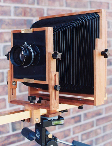
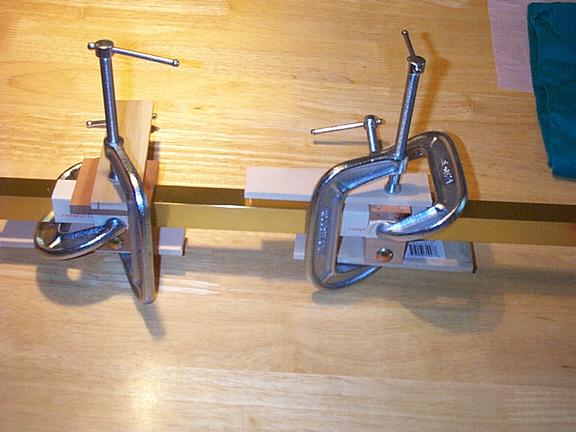
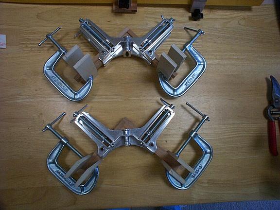
2) Lensboard HolderI assembled the lensboard holder using small pony right angle clamps rather than the "clamp the sections to a board method" Jay recommends. I glued the inner and outer boards on two sides at one time using a right angle clamp. I think this is the right way to assemble this piece because glueing these pieces at the same time allows them to interlock nicely both front to back and at the corner. I suspect that this method will result in a better corner joint. I assembled both assemblies this way, and after they dried, I glued the two assemblies together to form the lensboard holder. The sides and back were sanded smooth and flush. Using the right angle clamp the lensboard holder turned out square and the lensboard dropped into place. My lensboard was a bit too large to drop into place, even with almost no sanding to the ends of the lensboard holder pieces. A little sanding of the lensboard and it fell right into place. I did not drill and mount the lensboard latch pieces at this time, I did this piece at the end of assembly.
3) Back HolderThis was probably the hardest of the assemblies to construct. This is due to the inner pieces needing to be glued partway up the outer boards. Bender recommends marking and glueing the pieces, but any inconsistencies can mean gaps in the joints and a possibility of the back not being light tight. I took a different route. I took the ground glass holder pieces and used them as spacers for the back holder assembly. I first laid out all the pieces, and made sure I knew how they fit together. I used a pair of the 3/8" thick ground glass holder pieces placed under the inner wooden pieces. I glued a pair of the outer pieces together, then the inner pieces with the spacers under them. I pushed them together and downward. After a few minutes for the glue to setup, I clamped them together using a right angle clamp (upside-down) carefully making sure the inner pieces don't move, and the inner piece junction was properly positioned. I glue both sides of the back together, and after the glue dried, I glued the two assemblies together forming the back holder, also using the right angle clamps. Again, using the right angle clamps, the sides are square and the joints are clean, smooth and properly positioned. Very little sanding is needed. The two back attachment pieces are then glued into place. I carefully measured and centered these back pieces (part 11), then glued them in place.
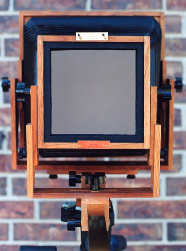
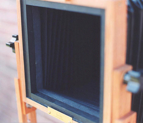
4) Ground Glass HolderAgain the four pieces which constitute the ground glass holder were sanded and glued using the right angle clamps. The bottom and top were sanded smooth and flush. The four tiny ground-glass spacers now need to be glued in place. The top face of the pieces have to be 15/64's above the bottom of the holder. Unfortunately the pieces are not 15/64's thick, which would be the best way to get consistent and accurate spacing. However I found a spacer that is perfect to place under the wood pieces to get the top exactly at 15/64's. I used a piece of 1/16" thick circuit board (copper both sides, FR4). Next, the ground glass retainer blocks need to be cut to shape. This is a bit of a pain, to cut out. The blocks are very small and need small cuts made in them. It would be really great if Bender would do this cut for us.
5) BackThe back was constructed in two pieces much like the lensholder frame and the back holder. However the right angle clamps can't be used here. I glued and clamped the pieces using the C-clamps. The ground glass holder and square were used to check the square of the back pieces. A belt sander would be really useful to notch the part 20's; I used the sandpaper on the boards. The ground glass holder spring retaining blocks were notched with the jigsaw in lieu of a lot of filing.
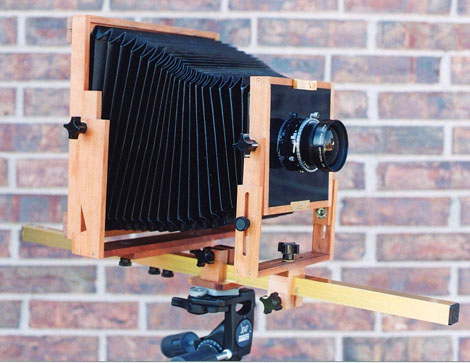
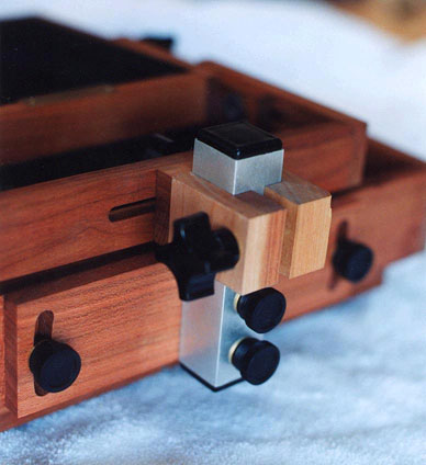
6) Front StandardThe front standard is glued together after sanding. I glued it together using the lensboard holder and other front standard parts bolted to the front standard sides to make sure the angles were correct. I glued it together and then clamped it while the glue dries.
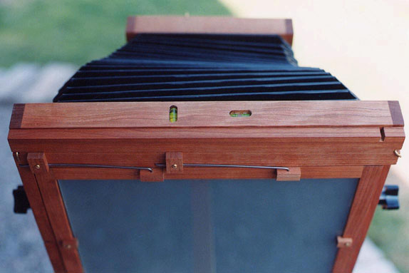
7) Rear StandardThe rear standard is glued together after the right upright is notched to allow the filmholder and darkslide to be removed if the back is angled upward. The angles of the rear standard uprights are held in place by bolting the uprights to the back holder.
8) Notching The BackI used a jigsaw to notch the back. I used a fine toothed metal blade to make two parallel cuts then the middle is chipped out. The L screws are mounted after drilling pilot holes for them. These holes should be drilled carefully, if the holes are drilled out too large (by wobbling a hand drill), the L screws are a bit too loose even with carefully drilled holes in my opinion. I think a slightly smaller drill bit should be used.
9) FinishingAs I stated earlier, I used Watco brand Danish Oil finish, and Watco wax. Some of the parts fit together with very little play the front rise and fall for example), and a finish that builds up the wood, will cause these parts to bind.
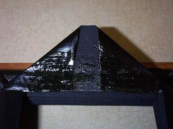
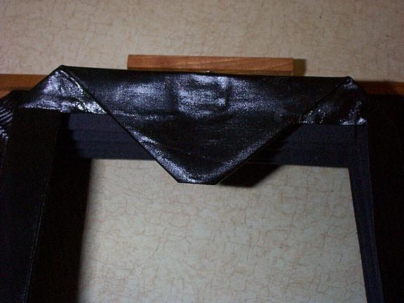
10) Painting Light TrapsThe best way to get clean edges on the light traps, is to mask off the areas that should not be painted. I used masking tape at the edges of the portions to be painted. After the paint is applied, the masking tape is removed before the paint hardens.
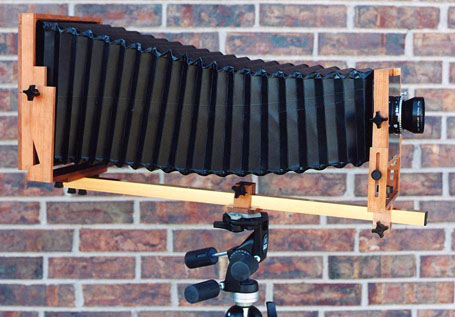
11) Mounting The BellowsThis is really the biggest shortcoming in the Bender manual. There is no description of where on the lensboard holder and back holder. Based on the size of the bellows at the back and front, it seemed that the bellows has to be glued to the front of the back holder, and to the rear of the lens holder. I thought that the bellows would be glued to the inside surfaces, but it was too large to fit through the square openings. There is no discussion of what type of glue to use either. I used contact cement, which bonds nicely, but has very little ability to move the pieces after they have been joined. So the bellows should be very carefully aligned before pushed together. I trimmed the excess material off the front and back of the bellows in places. I trimmed the material off the sides where the pleats are pushing inward. I left the material long and folded it over on diagonals in the shape of an envelope flap. I glued these flaps in place, and folded the rest of the material over toward the inside of the bellows. This technique doubles over the corners and makes the edges clean looking from the side. The perimeter is coated with contact cement, as is the wooden piece. After the glue is tacky, the two pieces are very carefully positioned and pressed together. I couldn't see how using Bender's technique that the corners could be satisfactorily glued into place.
12) Mounting The LevelsI used rubber cement to mount the levels, I wasn't sure if I would need to remove them or readjust them, so I used rubber cement.
13) Final Adjustment Of The Ground GlassUsing Bender's techniques I checked my ground glass spacing, and surprisingly, it was right on. I credit the circuit board spacers more than my assembly techniques.
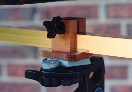
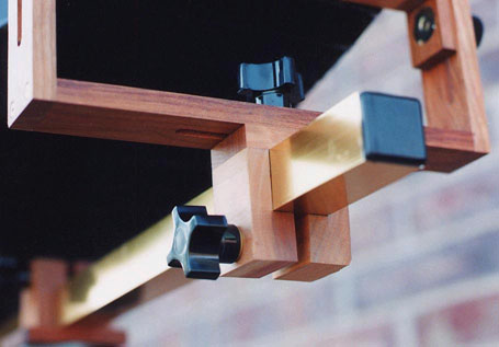
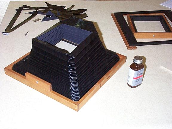
14) My ImprovementsFirst, because I want to use this camera in the field, I need to collapse the camera. This is easily done by removing the front and rear standards from the monorail and collapsing the bellows. The camera (sans rail) then collapses into a 5" x 15" x 16" package. However, the wooden parts can rub and bang into each other damaging the hard work done constructing this beautiful and functional camera. My solution was to construct a very short monorail to attach both standards to. I bought a piece of the monorail material at Home Depot, and cut it to 4" long. I then drilled two holes to mount the rear standard. I also put plastic end plugs in the rail section. This allows me to mount the two standards on this rail, the standards are fully collapsed and held in place to protect them. I don't particularly care for the L-screws holding the back in place. I couldn't find any hardware that I thought would look good and do a better job so I went with the L-screws. I would prefer a two threaded knobs with 4 t-nuts on the back holder. I'm considering some changes to the ground glass springs, the ground glass frame springs take a lot of force to wrangle a film holder into place. And if the movements aren't very securely tightened down, the back can move. Probably the biggest change I've made to the camera is to add sandpaper friction pads to the movements. Using danish oil and wax to finish the wood causes the wood surface to be very slick. Consequently, the knobs have to really be tightened down excessively hard to really lock the movements. The front swing movement could easily be loosened by pressing the right front standard upright forward (no matter how tight the knob was). My solution for the front standard swing and shift adjustment is to glue two 1" x 1/2" pieces of 220 grit sandpaper to the top of the front standard monorail rider covering the countersunk screw heads. The sandpaper contacts the bottom of the front standard and hold it very securely in place with only moderate knob tightening. I noticed that I moved the front standard slightly while wrestling my big copal 3 shutter into the right shutter speed. I also glued a piece of 3/4" x 1/2" 220 grit sandpaper to the underside of the rear standard between the two threaded inserts where it contacts the monorail. This only moderately helps to secure the rear standard. Most importantly, I glued 220 grit sandpaper to both sides of the washers between the lensboard holder and the front standard. I did the same thing to the washers that hold the rear portion of the camera to the rear standard. This allows the front and back of the camera to be securely locked down with only moderate knob tightening. I used 220 grit sandpaper, I'm not sure this is the ideal grit. I suspect 150 may be better. I'm also not sure how the sandpaper will hold up over time. I have a sneaky suspicion that the grit will wear off pretty quickly. Something like emory cloth may be a better idea. 15) ConclusionsIn conclusion, I found the bender kit to be well engineered, and the parts supplied to be very well constructed. I didn't find the lack of extremely explicit instructions to be a problem (As an engineer, I prefer it that way), but those without a lot of experience should understand that this isn't a small or simple project. The directions are well done, and if followed should allow most anybody to build a functioning camera. The camera has a completely different feel than my Linhof Technica (don't forget the smaller Technica also costs an order of magnitude more), but that's to be expected as this is a wooden camera. The movements have a bit of a spring and a give that the Technica doesn't have. However the movements don't slip, and in my experience spring back into position after the force is removed. It's a bit worrisome to see the rear standard flex when putting in a large film holder, especially after using the rock solid Linhof. But to the Bender's credit, it springs right back to it's original position and the pictures have always been sharp. |
Home
You are guest number:
[an error occurred while processing this directive]
[an error occurred while processing this directive]