Quad ESL Service Manual
Click on the figures to download a higher resolution version
|
This information was graciously provided to me by: Rolv-Karsten Roenningstad Carl Kjelsensvei 77 N-0880 Oslo Norway Tel. +47 22 95 05 14Rolv.Roenningstad@alcatel.no |
Servicing Quad Electrostatic Loudspeakers
A Web Quad ESL Service Manual
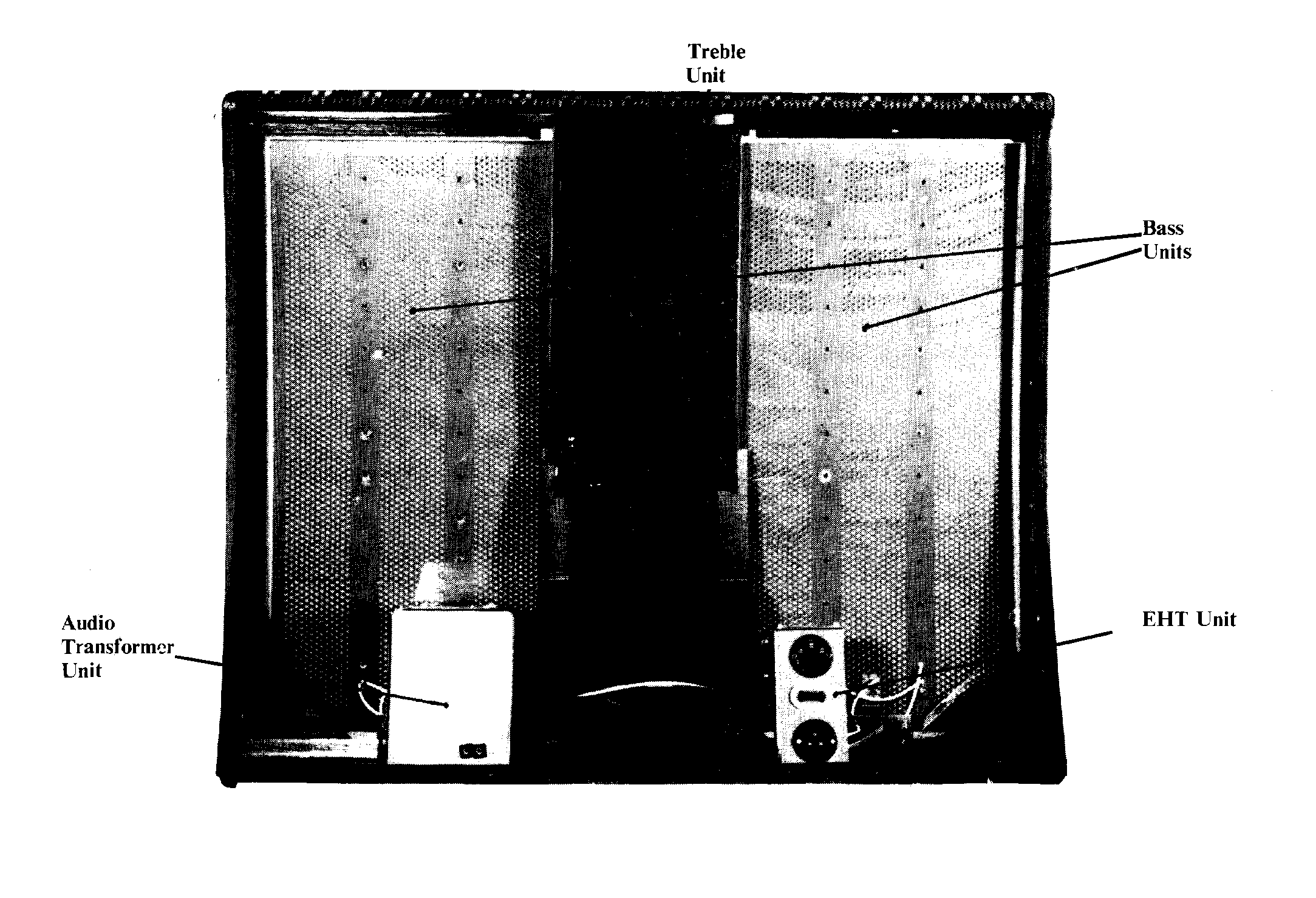
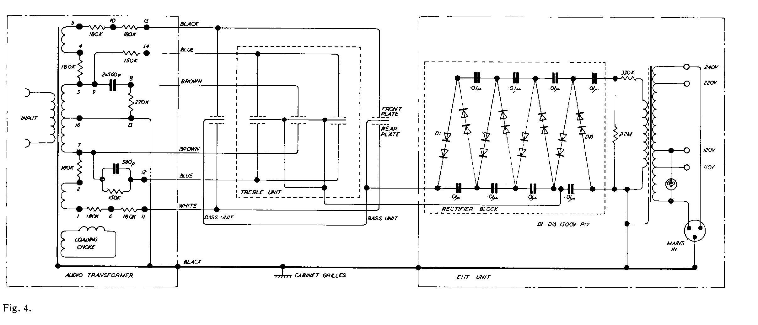
The QUAD electrostatic speaker consists of five components: two bass units, one treble unit, an audio transformer unit and an EHT supply unit. If any repairs are necessary, it should be ascertained which of the five components is the cause and that component should be either replaced complete or repaired as appropriate.
The following notes may assist diagnosis of faults:
Loss of Sensitivity
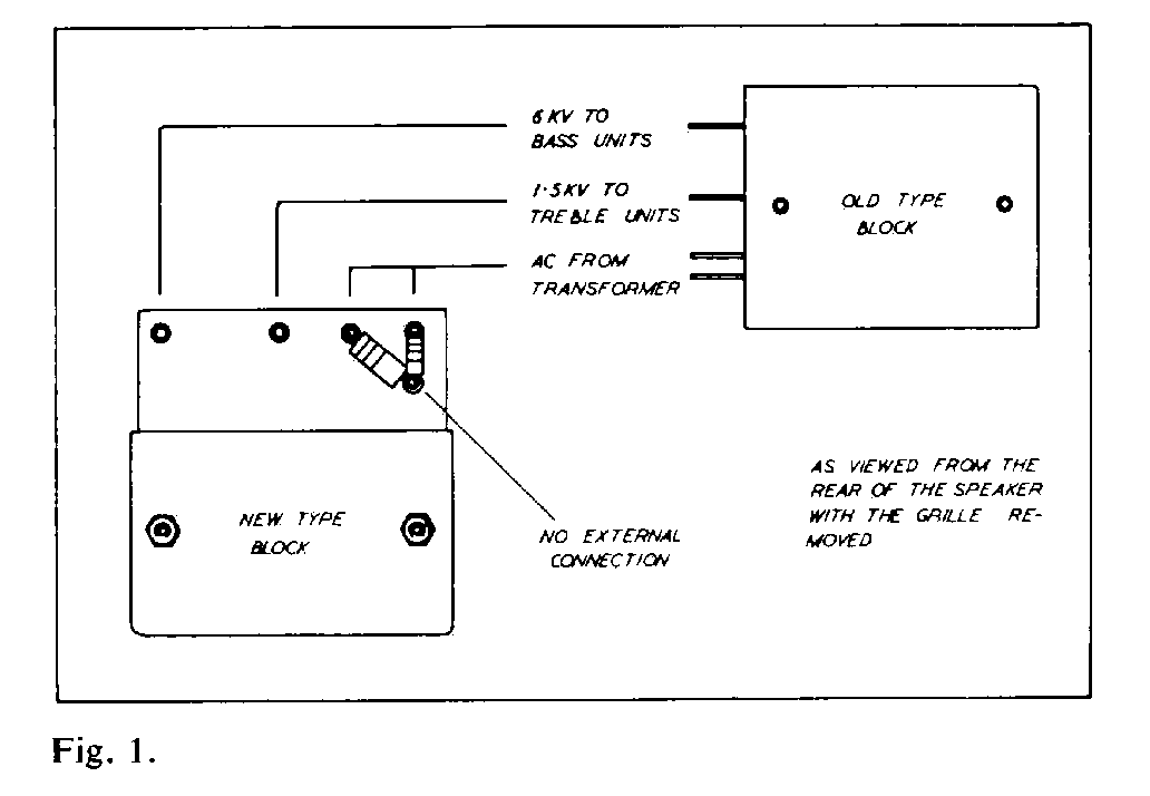
Check the EHT voltage, which should be: Bass 6Kv ± 7%; Treble 1×5Kv ± 7 %. If low, check, by disconnecting, whether due to leakage in speaker unit or fault within EHT unit. Voltages must be checked only with electrostatic meters, as the current drawn by other types may itself damage the rectifiers.
Distortion
- Make sure that the speaker is really at fault by comparison with a second electrostatic speaker, using a QUAD amplifier.
- Check EHT voltage
- Suspect intermittent breakdown in speaker units.
- Suspect intermittent breakdown in audio transformer unit. (Note: a fault in this unit is very unlikely).
No output at all
Suspect EHT unit or audio transformer unit after checking more obvious things like external connections, not forgetting the leads under the transformer unit connecting the input sockets.
Background Noise
One cause of background noise in the electrostatic loudspeaker is internal discharge of the EHT supply at times of high humidity, or high voltage, or both. This may be reduced by lowering the EHT voltage and a tap is provided on the EHT mains transformer for this purpose. The connections to the EHT rectifier block are normally taken from tags marked Common and 610V. The latter is the right-hand end tag and next to it is a blank tag marked 590V to which should be transferred the lead normally connected to the 610V tag.Before the EHT unit is touched the mains should be completely disconnected and the loudspeaker left to stand for two hours to ensure it is completely discharged.
Background noise may also be caused by discharge of the EHT from points external to the loudspeaker units, at the tags on the rectifier block for example, if a hair of felt or piece of fluff comes in reasonably close proximity to that point, or if a spike of solder or sharp point of wire permits corona discharge.
Where EHT leakage occurs via a bass unit, this is sometimes found to be discharging from one of the eyelets around the periphery of the bass unit plates, probably to one of the aluminium brackets. In such cases a satisfactory repair can be effected by slitting the polythene tape round the edges of the unit, opening the dustcover frames and insulating the leak by applying a single layer of similar polythene tape all round the periphery of the internal plates, on top of the existing sealing tape, and reassembling the dustcovers, again with polythene tape.
Other internal failures of insulation will probably necesitate replacing the loudspeaker unit affected.
Mechanical
If the dust seal covers should be torn, it may be necessary to replace the complete unit as there will have been ingress of dust, which causes loss of sensitivity of the unit concerned.
DISMANTLING THE SPEAKER
The loudspeaker should be switched off for about two hours before the grilles are removed, so as to ensure the EHT unit has completely discharged.The component loudspeaker units of the QUAD electrostatic loudspeaker must be handled with the utmost care partly because when not supported by the rigid frame of the cabinet they are more liable to physical distortion which would reduce the small internal clearances, and partly because the dust covers are necessarily made of very thin and therefore fragile plastic film.
At the rear of the treble unit are four pins, located in the wooden struts of the cabinet, and as these represent an additional hazard to the dust covers of the treble unit, the positioning of this unit requires particular care.
Soldered joints should be smoothed and rounded and all spikes of solder, wisps of wire, etc., removed as these would tend to cause arching at the high internal voltages used.
Removing Front and Rear Expanded Metal Grilles
The rear grille is held only by the screws around its periphery. For the front grille it is necessary first to remove the side mouldings, the staples through the metal beneath them, and the screws under the baseboard. Then the bottom edge of the grille is lifted gently outwards and upwards until the top rear edge may be slipped out of its groove in the cabinet, when the whole grille will be free. Care must be taken not to strain the top curved section during removal or the metal may split.
Replacing the Front Grille
Replacement grilles are normally supplied cut and pre-formed so the procedure is as for refitting an existing grille. It may be found helpful when working single handed, having inserted the top back edge of the sheet into the slot in the cabinet, to hold the bottom edge of the grille under slight tension to the bottom of the wooden frame by means of elastic bands and simple hooks of wire, such as an opened paperclip, and then to use a bar of wood slightly longer than the width of the sheet, and with a good flat face, to bed the grille to the frame by moving the bar progressively down the face of the grille, tacking the sides as you go, finally securing the bottom edge with the screws removed from the old grille. Do not forget to fasten the earthing lead to the grille.
Replacing Bass and Treble Units
- Remove both grilles.
- Remove the top and bottom aluminium brackets in front of the centre (treble) unit.
- If the treble unit is to be replaced, it should now be disconnected from the audio transformer (the large rectangular can on the left-hand side when viewed from the rear). This is held in position solely by four screws whose heads are accessible below the baseboard of the speaker. If the speaker is tilted to provide access to slacken these screws it must be restored to its upright position before they are removed or the transformer will have no support other than its connecting wires.
- Carefully prise out one bass unit and slide it past the front of the treble unit until the outer edge clears the remaining bracket at top and bottom of the cabinet.
- Either disconnect and remove the bass unit if this has to be replaced or move it far enough to enable access to be obtained to the treble unit, as required. To remove the treble unit ensure it is free of the four pins mentioned on page 3, then slide it sideways into the space vacated by the bass unit already moved and lift it out.
EHT and Audio Transformer Units
Only the rear grille need be removed to provide access to these units. Both are secured by screws through the base board only and if the speaker is tilted to obtain access to these screwheads it must be restored to the upright position before the screws are removed or the unit will have no support other than its connecting wires.Place a sheet of cardboard behind the EHT unit to protect the thin plastic dustcover of the bass unit from accidental damage due to specks or solder of wire ends. Etc.
Note and mark the flexible connections to the rectifier block so as to ensure correct reconnection.
Reassembling the Speaker
To reassemble, the dismantling procedure is reversed, but in addition it will be necessary to remove any wrinkles which may have appeared in the treble unit's front and rear dust covers, as these will produce audible rattles when the speaker is in use. This is achieved by means of gentle heat which thermosets the plastic film, and may most conveniently be applied by means of a small warm air blower, such as a hand-held dryer. The nozzle should be held about 18 from the dust cover and moved up and down the unit as uniformly as possible at a speed of about 3" per second, in regular lines so as to cover the whole area. Repeat until all wrinkles have disappeared, but always treat the whole area and do not tackle individual wrinkles separately.A certain amount of skill is required in this operation. Obviously if the nozzle is not close enough and/or the speed of travel too great, there will not be enough heat to affect the cover. On the other hand too much heat at one point can quickly burn a hole. When carrying out this process for the first time, progressively reduce the distance and speed until the desired results are obtained.
Heat should not be applied to the bass unit covers. Any slight wrinkles in these covers will rarely have any audible effect and will in any case normally disappear as the tensions even themselves out in a few days. After thermosetting the treble unit dust covers, the damping felts behind the treble unit must be stretched and fixed so that there is no contact between them and the treble dust cover, as this will also affect reproduction.
Fitting New Dust Covers
Note: The plates and dust cover material acquire a static charge and if placed in a dusty atmosphere or near any accumulation of dust it will adhere to them, with deleterious effects. Only plastic film supplied by Acoustical should be used. Specify whether for bass or treble unit when ordering.First remove the faulty unit from speaker as described on page 4, and strip the adhesive tape from around its edges to release the two dustcover frames. On bass units carefully disconnect the three wires from the terminal board, having noted their positions, and remove the board. Clean all loose dustcover material from the wooden frames since any pieces left to flap will buzz.
Spread enough of the new dust cover material on to any clean, solid, flat surface to leave about 6" surplus all around the frame, and hold in position with pieces of adhesive tape at each corner and at intervals along the sides as required.
The materials should not be over stretched but just tightly enough to remove the wrinkles.
Adhesive can now be applied to the frame, the frame placed into position on the material and left to dry. The adhesive should preferably be of a type which does not set brittle, such as Samual Jones' Samson C203, Evostick, etc. When this is dry, use a razor blade to trim off all surplus cover material back to the edge of the frame. The holes to the terminals should be BURNT through the film with a small soldering iron. If pierced cold the material will in time split and run the whole length of the dust cover.
When a pair of covers have been made, the unit and the covers should be blown with a jet of dry air to remove any dust particles etc., which have adhered to them, as this will cause a loss in sensitivity.
GREAT care should be taken if it is found necessary to renew any soldered joints on the plates. Anything more than a quick touch to the tags will soften the plate material and loosen the solder tag. A heat sink is helpful here.
When reconnecting to the terminals be sure not to cross wires as this will result in the failure of the speaker to work.
The unit should be replaced between the two frames and sealed with 2~ wide polythene adhesive tape all around the outside edge of the frames as before.
This completes the recovering and the unit can now be reassembled into position in the speaker.
Modifications
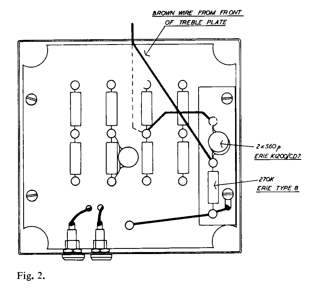
At serial number 16800 (March 1966) additional filtering was added to protect the treble unit from damage due to high level low frequency signals. Earlier speakers may be modified as described below, when they are to be used with the Quad 303 or other suitable amplifiers of comparable output.

- Remove the mains supply from the speaker and allow two hours for the EHT to discharge.
- Undo the screws all around the periphery of the rear grille and remove the grille.
- Tilt the loudspeaker to permit access to the underside of the baseboard. taking care not to dent the front grille.
- Remove the four screws holding the audio transformer (large can on the left hand side) in place, remembering to support the transformer before it is freed or it may slip and damage the left hand bass unit dustcover.
- Restore the speaker to an upright position and invert the audio transformer, taking care not to strain its external wiring.
- Remove the two drive screws on the right-hand side of the tagboard and use these to secure the small tagboard supplied, as shown in Fig. 2.
- Rewire as shown, ensuring that the brown lead which has to be stretched to reach its new anchor point does not press against any sharp edges of turret lugs or solder.
- Re-assemble the speaker in the reverse order of operations 1 to 5.